XOD support for the starter board
Port connections:
1. LED
2. Buzzer
The piezo can be connected to digital outputs and will emit a tone when the output is high. Alternatively, it can be connected to an analog pulse-width modulation output to generate various tones and effects.
3. OLED
The OLED Display 0.96" (SSD1306) is a monochrome(white) 128×64 pixels display matrix module with I2C Interface.
wayland/ssd1306-oled-i2c@0.0.7
License: BSD
Arduino library for OLED displays driven by the SSD1306 chip. Communication via I2C. Wraps Adafruit_SSD1306 (https://github.com/adafruit/Adafruit_SSD1306).
Node
Description
clear-display: Clear contents of display buffer (set all pixels to off). Changes buffer contents only, no immediate effect on display. Follow up with a call to send-buffer-to-display, or with other graphics commands as needed by one's own application.
dim-display: Dim display. This has an immediate effect on the display, no need to use the send-buffer-to-display node -- buffer contents are not changed.
draw-circle: Draw a circle. Writes data to display buffer. To show content of display buffer on screen use node send-buffer-to-display.
draw-line: Draw a line. Data written to display buffer. To show content of display buffer on screen use node send-buffer-to-display.
draw-pixel: Draw a pixel.
draw-rectangle: Draw a rectangle. Writes data to display buffer. To show content of display buffer on screen use node send-buffer-to-display.
draw-rounded-rectangle: Draw a rounded rectangle. Writes data to display buffer. To show content of display buffer on screen use node send-buffer-to-display.
draw-text: Writes string to display buffer. To show content of display buffer on screen use node send-buffer-to-display.
draw-triangle: Draw a triangle. Writes data to display buffer. To show content of display buffer on screen use node send-buffer-to-display.
draw-xod-logo: Draw XOD logo. Logo is 128 x 64 pixels.
example-draw-shapes: Draw shapes in proportion to display size.
example-rotate-display: Text will be drawn in two different directions.
example-scroll: Performs a diagonal right scroll for 30 seconds, then stops scrolling.
example-xod-logo: Display and inversion of XOD logo.
get-display-dimensions: Get dimensions of display in pixels.
invert-display: Enable or disable display invert mode (white-on-black vs black-on-white). This has an immediate effect on the display, no need to use the send-buffer-to-display node -- buffer contents are not changed, rather a different pixel mode of the display hardware is used. When enabled, drawing BLACK (value 0) pixels will actually draw white, WHITE (value 1) will draw black.
rotate-display: No description
send-buffer-to-display: Push data currently in RAM to SSD1306 display. Drawing operations are not visible until this function is called. Call after each graphics command, or after a whole set of graphics commands, as best needed by one's own application.
ssd1306-oled-i2c-device: Create SSD1306 OLED device.
start-scroll: Activate scroll for all or part of the display. To scroll whole display set FIRST to 00h and LAST to 0Fh.
stop-scroll: Stop scrolling.
4. Button
The Grove Button is a momentary push button. It contains one independent "momentary on/off" button. “Momentary” means that the button rebounds on its own after it is released. The button outputs a HIGH signal when pressed, and LOW when released.
5. Potentiometer
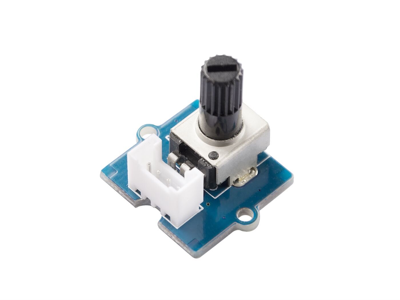
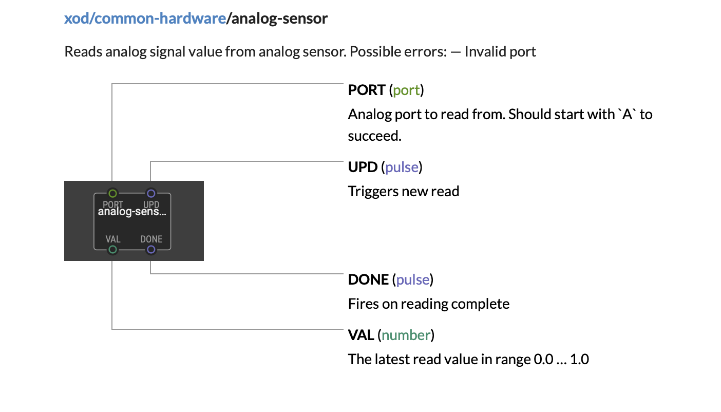
The potentiometer or pot, consists of an internal resistive element called the track and a sliding contact called the wiper where end terminals are attached to the resistive element. These allow the output of a variable voltage that is converted to an output value of 0 to 1.
6. Light sensor
Description
The Grove - Light sensor integrates an LS06-S photo-resistor (light dependent resistor) to detect the intensity of light. The resistance of photo-resistor decreases when the intensity of light increases. A dual OpAmp chip LM358 on board produces voltage corresponding to the intensity of light (i.e. based on resistance value). The output signal is analog value, the brighter the light is, the larger the value, with a short response time: 20 ~ 30 milliseconds.
The device is connected to analog port 6 on the Beginner board. This is usually not connected on Arduino UNO compatible boards, so you should use a custom analog read node that has been written by Matt Wayland (https://xod.io/libs/wayland/analog-read-no-port-check/). This allows the output voltage of the sensor to be converted to a digital signal by the analog-to-digital-converter on your controller board.
7. Sound sensor
Grove - Sound Sensor can detect the sound intensity of the environment. The main component of the module is a simple microphone, which is based on the L358 amplifier and an electret microphone. This module's output is analog and can be easily sampled and tested by an Arduino microcontroller.
8. DHT11 Hygrometer
Description
Grove - DHT11 Temperature & Humidity Sensor is a high quality, low-cost digital temperature, and humidity sensor based on the DHT11 module.
DHT11 is the most common temperature and humidity module for Arduino and Raspberry Pi. It is widely favored by hardware enthusiasts for its many advantages such as low power consumption and excellent long-term stability. Relatively high measurement accuracy can be obtained at a very low cost. The single-bus digital signal is output through the built-in ADC, which saves the I/O resources of the control board.
The Grove - Temperature & Humidity Sensor uses an upgraded version of DHT11. The new version of the DHT11 module replaces resistive humidity components with capacitive humidity components. The temperature and humidity measurement range are wider. The temperature resolution is higher.
XOD library
xod-dev/dht@0.36.1
Nodes to work with DHT11 or DHT21 sensors, or compatible sensors: RHT01, DHT22, DHT33, DHT44, AM2301, HM2301, AM2302, AM2303, RHT02, RHT03, RHT04, RHT05.
XOD Nodes
dht11-device: Represents a DHT11 sensor. Also named RHT01.
dht11-hygrometer: Read the temperature and humidity by the DHT11 (RHT01) hygrometer sensor.
dht2x-device: Represents a DHT21 or compatible sensor: DHT21, DHT22, DHT33, DHT44, AM2301, HM2301, AM2302, AM2303, RHT02, RHT03, RHT04, RHT05.
dht2x-hygrometer: Read the temperature and humidity by the DHT21 or compatible (DHT21, DHT22, DHT33, DHT44, AM2301, HM2301, AM2302, AM2303, RHT02, RHT03, RHT04, RHT05) hygrometer sensor.
example-dht11: No description
read: Reads the temperature and humidity.
read(dht11-device): Reads the temperature and humidity.
read(dht2x-device): Reads the temperature and humidity.
9. Air pressure sensor
Description
The Grove BMP280 Barometer Sensor is built around Bosch BMP280, it is a low-cost and high-precision environmental sensor that measures the temperature and air pressure. This sensor supports both I2C and SPI communication using a custom BMP280 Arduino library.
Grove BMP280 provides precise measurements of barometric pressure and temperature in the environment. The air pressure can be measured in a range from 300 hPa to 1100hPa with ±1.0 hPa absolute accuracy. It also provides a temperature readout, for temperatures between - 40℃ and 85℃ with an accuracy of ±1℃.
Owing to its high accuracy in measuring air pressure, and known pressure changes with altitude, one can calculate the altitude with ±1 meter accuracy, which makes it a precise altimeter as well. It provides both I2C and SPI interfaces for communication with the microcontroller. The board provides alternative I2C addresses.
https://ae-bst.resource.bosch.com/media/_tech/media/datasheets/BST-BMP280-DS001.pdf
XOD library
wayland/bmp280-barometer@0.0.1
Library authored by Matt Wayland for the BMP280 barometric pressure and temperature sensor. Converted from https://github.com/adafruit/Adafruit_BMP280_Library.
bmp280-device: Create BMP280 device. See datasheet (https://ae-bst.resource.bosch.com/media/_tech/media/datasheets/BST-BMP280-DS001.pdf) for recommended oversampling and filter settings for specific use cases.
calculate-altitude: Calculate altitude from atmospheric pressure.
read-pressure: Read pressure in Pascal.
read-temperature: Read temperature in degrees Celsius.
example-oled-altimeter: Uses bmp280 as an altimeter and displays altitude on an OLED screen.
barometer-thermometer: Combines low level nodes to create a simple to use barometer and thermometer.
example-test-barometer-thermometer: Patch to test barometer-thermometer node. Run in debugger.
10. LIS3DHTR accelerometer
Description
The Grove 3-Axis Digital Accelerometer contains a low-cost 3 axis accelerometer (LIS3DHTR). It is based on the LIS3DHTR chip which provides multiple measurement ranges: ±2g, ±4g, ±8g, ±16g. The tiny 3 - Axis accelerometer can support I2C, SPI, and ADC GPIO interfaces, which means you can choose any way to connect with your development board. In addition, this accelerometer can also be temperature compensated to tune the errors.
XOD library
wayland/lis3dh-accelerometer@0.0.1
Authored by Matt Wayland to support the LIS3DH triaxial accelerometer. Wraps https://github.com/adafruit/Adafruit_LIS3DH.
accelerometer: Combines lower level nodes to create a simple to use accelerometer.
click-detector: Combines low level nodes to create a simple to use click-detector. Detects single or double taps of the sensor.
example-read-adc: Patch to test read-adc node. Run in debugger.
example-read-raw: Patch to test read-raw node. Run in debugger.
get-click: Detect single or double "click" (tap).
get-data-rate: Get data rate.
get-device-id: Read the ID of the lis3dh device.
get-range: Read the g range for the accelerometer.
lis3dh-device: Create a lis3dh device.
read-acceleration: Read acceleration (metre per second squared) in all three axes.
read-adc: Read the auxiliary analog-to-digital converter.
read-raw: Read X, Y and Z raw values.
set-click: Configure parameters for "click" (tap) detection. See datasheet for explanation of parameters: http://www.st.com/resource/en/application_note/cd00290365.pdf
set-data-rate: Set data rate.
set-range: Set range.
example-motion-detector: Demonstrates how lis3dh can be used as a motion sensor. LED is illuminated if motion is detected. Push button resets motion detector.
example-test-accelerometer: Test of accelerometer. Run in debugger.
example-test-click-detector: Test of click-detector. Run in debugger.
example-tweak-settings: Demonstrates changing data-rate and range at runtime using tweak nodes. Run in debugger.
11. Seeeduino Lotus microcontroller board
The Grove Beginner’s kit contains an embedded microcontroller board that is based on the Seeeduino Lotus ATMEGA328 development board. It is a combination of Seeeduino and Base Shield. The Seeeduino Lotus v1.1 uses a high performance, low power AVR 8-Bit Atmel ATMEGA328P-MU chip and Silicon Labs CP2102N USB-to-serial interface chip for laptop communication. The Seeeduino Lotus has 14 digital input/outputs (6 of which can output PWM) and 7 analog input/outputs, a micro USB connection, an ICSP header, 12 Grove connections, a reset button. More information about the component can be found on the Seeed Studio wiki site:
https://wiki.seeedstudio.com/Seeeduino_Lotus/


