
Design of air flow based microreactors
Temperature-controlled incubation of enzyme reactions are a key part of any molecular biology workflow. These might range from simple digestions at 25ºC to 37ºC, but the advent of polymerase chain reaction (PCR) for DNA amplification in the 1909's triggered the development of a range of more capable instruments that could rapidly and accurately through higher temperatures 50ºC to 95ºC. Sophisticated devices with Peltier devices and electronic feedback for temperature control have become routine fixtures in modern labs. However, these can be relatively expensive for researchers and educators/students in low resource settings.
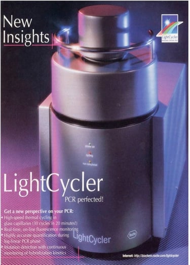
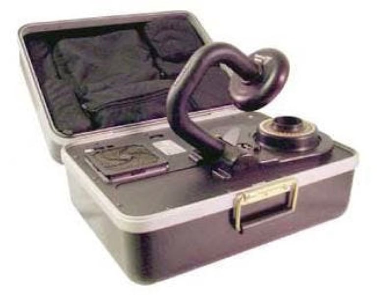
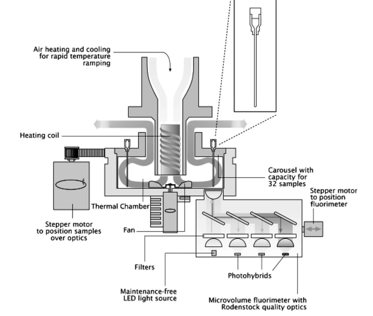
One early strategy for temperature control exploited the use of circulating hot and cool air to incubate PCR reactions. For example, hand-built prototypes used hair dryer and vacuum cleaner parts for controlled air flow (see below). This approach led to a more refined commercial instruments - including the Roche LightCycler (below) and the Corbett RotorGene, some of the first PCR instruments with real-time fluorescence monitoring of DNA amplification.
Instruments based on air flow heat transfer have largely been supplanted by direct contact with machined metal blocks and Peltier based heating/cooling. However, the wide availability of 3D printers, high temperature-resistant filaments and cheap electronic controllers suggested that these early ideas might be worth revisiting for the design of modern low cost devices.
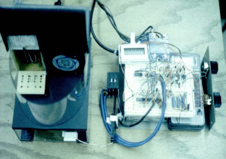
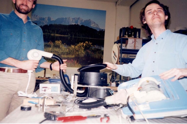
“For a real-time system, the light bulb in the thermal cycler had to be replaced with another source of heat. We went back to the hair dryer concept. The dryer and vacuum cleaner were connected to the center drum by vacuum hose tubings. This contraption was so loud! It was remarkable that it worked as a thermal cycler.”
Carl Wittwer Lab, University of Utah https://arup.utah.edu/media/rapid_pcr/rapid_pcr_slides.pdf

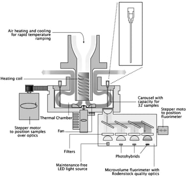
Early trials
In 2020, the onset of the COVID pandemic triggered great interest in accessible diagnostics. One of the challenges was to find ways of building instruments for running temperature-controlled LAMP and PCR reactions in low resource environments. Such instruments would have wide applications in other areas of molecular engineering too. Starting from a self-admitted naive position, I explored a series of investigations, starting with simple vessels with heater and recirculating air through to experiments with different geometries, types of fan, heat sinks, manifolds, 3D printed materials and microreactor features. These have been documented in a series of technical posts on Hackster.io, linked below. The exploration and testing of various in design strategies and use of different off-the-shelf components could be of interest to other builders...
Summary of Airflow Reactor development: Testing construction principles for building open source, low-cost microreactors for biological diagnostics and DNA engineering.
AirLoop I (Part 2): Attempt to build an ultra-low cost molecular reactor, using computer controlled recirculating air.
Radial Airflow Incubator (Part 3): Design of a low cost incubator with heated radial airflow for molecular diagnostics.
Heatsinks for Microreactor Temperature Control (Part 4): Testing different heatsinks for temperature control by forced air convection in low cost microreactors.
Modular Microreactors (Part 5): Testing designs for low-cost microreactors for biological diagnostics and DNA engineering.
Microreactor heating and airflow circuits (Part 6): Design and testing of alternative air heating and recirculation systems for low-cost instruments for molecular diagnosis and DNA engineering.
Thermal Cycling Airflow Reactor I (Part 7): Part of a challenge to build low-cost microreactors for DNA engineering, this project explores switched airflow to build a thermal cycler.
Thermal Cycling Airflow Reactor II (Part 8): Adding an airflow manifold to a very low cost microreactor, designed for DNA assembly, PCR and programmable biology.
Refactoring the Airflow Reactor design (Part 9): Redesigning the Airflow reactor for final testing and open application development.
Airflow reactor manifolds (Part 10): Testing 3D printed manifolds for the AIrflow Reactor: part of a project series to build low cost devices for DNA engineering and diagnostics
High static pressure fans for the Airflow Reactor (Part 11): Testing upgraded fans for better forced convection and improved heat transfer in 3D printed reactor vessels.
Redesigning flow channels for the airflow reactor: Improvements in switched air flow for a low cost device for DNA engineering and diagnostics.
The experiments were consolidated in the design of an isothermal incubator that was built from heat resistant 3D printing filament, 50W car window heater, computer tangential fan with electronic sensor, XOD software control and display, and documented here on Hackster:
AirFlow microreactor: Working low cost device for constant temperature incubation of micro reactions, including LAMP molecular diagnostics.
The construction of the device was also documented in the Biomaker handbook for Rapid Prototyping, and the relevant extract can be downloaded here as a PDF. The instrument is relatively low cost, even cheaper if one economises with the display, is temperature-accurate and works well for running LAMP diagnostic reactions, for example. The design has provided a springboard for further work to include heating and cooling cycles, and to develop a cheap airflow instrument capable of PCR amplification of DNA, and other reactions that require higher temperatures or cycling.


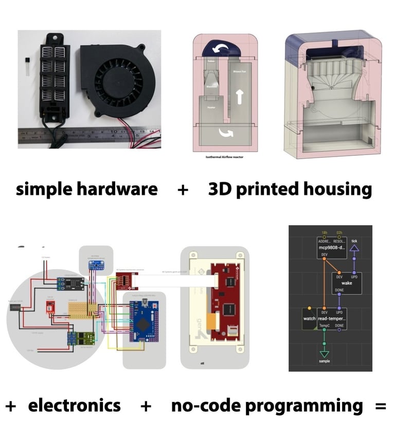
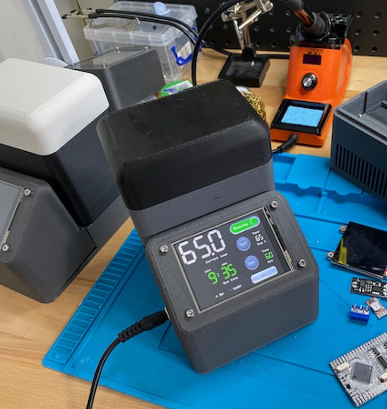
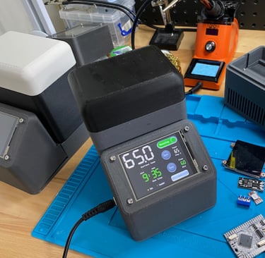
Building the AirFlow isotherm microreactor
Earlier prototyping experiments (see Background section below) have led to the current design of a programmable thermal reactor that allows microtube reactions to be incubated in a constant temperature air flow. The objective was to build a device that included:
Space for at least one 8-microtube strip that takes up a volume of approximately 80x30x10mm - with allowance for possible future integration of optical sensors or cheap plastic fibre optics.
An off-the-shelf PTC resistive element as heat source.
Unidirectional fan-forced air flow through the device, using a low-cost computer blower fan.
Minimal volume of air for recirculation, to improve response to heating (or cooling).
An accurate thermal control system using low-cost Arduino electronics and sensors.
Touchscreen microcontroller interface that allowed easy use of the programmable device.
Attempt to minimise costs of construction and use components that are globally accessible.
The use of 3D printing, no-code programming, commodity electronics and open source documentation to allow free sharing and modifications of the design.
The project aimed to explore different components, designs and practical assembly of low-cost microtube incubators - which would make accessible a new generation of isothermal reactions - for home testing, field applications and international educational efforts.
Instrument design
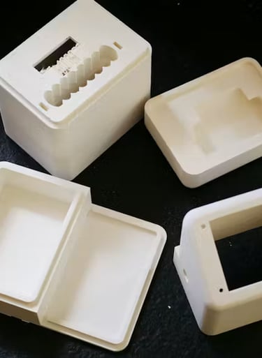
The core of the instrument is a rack for an 8-microtube strip inside a modular 3D printed set of blocks that create a physical loop for air flow - with temperature control by a computer controlled heater and forced air flow by a blower fan.
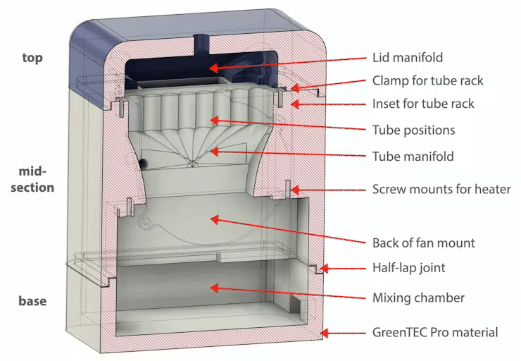
The device consists of sections that slot together with half-lap joints defined in the 3D print files. Exterior walls are 8mm thick, with 3.75 mm flanges at the overlap between section, allowing 0.5 mm gap between half-lap joint pieces, which are 5mm deep. This allows sufficient clearance to avoid problems with fitting of curved pieces, and allows the sections to be simply stacked on top of each other to create a fairly stable and air tight joint. This is very useful during prototyping, but might be replaced by something more permanent in a finalised design.
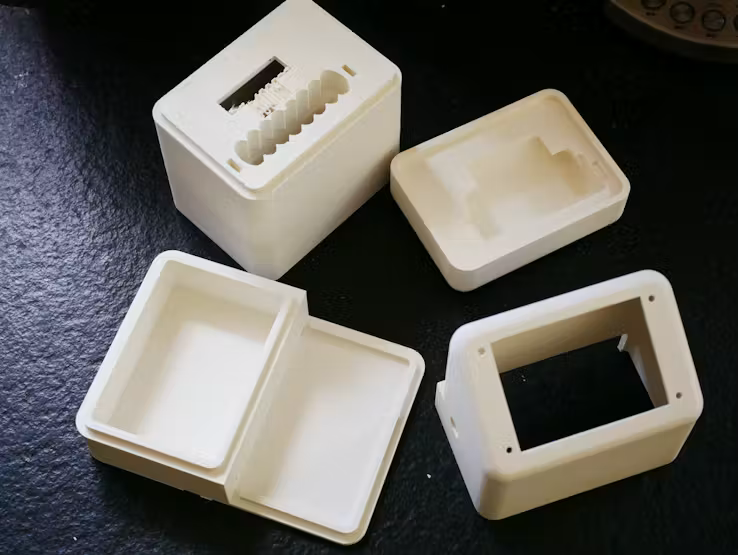
The sections consist of (i) a base plate with an extended front deck for the electronics, (ii) a mid-vessel sections sits above this and contains the heater and fan, and support for the microtube rack. (iii) A custom lid sits above this, and contains streamlined venting to direct forced air flow between the fan and heater compartments. (iv) A front console sits on the front part of the base section, This provides a support for the integrated touchscreen and a housing for the instrument electronics.
The AirFlow parts can be printed in a variety of different materials, but care must be taken if the reactor is to be used at temperatures over 70ºC, where commonly used materials such as PLA will start to soften and deform, and may even melt. I have settled on Extruder GreenTEC Pro filament, which is relatively resistant to heat up to 160ºC (VICAT softening temperature: at which a specimen is penetrated to a depth of 1 mm by a flat-ended needle with a 1 mm² circular or square cross-section - but I try not to stray too much above 100ºC). GreenTEC Pro is also derived from renewable raw materials and is biodegradable. The material is very easy to print with and produced a matt finish which is easy to work with tools or smooth with abrasive pads after printing.
The components are relatively large and can take over a day to print. Print failures were minimised by the use of a print bed adhesive. I have found that Dimafix is an excellent adhesive for use with GreenTEC Pro filament on the heated glass bed found on the Ultimaker S3. The build is released after printing by cooling or refrigerating the plate. Printing is generally trouble-free. Also, GreenTEC Pro Carbon is available for stronger carbon-fibre-infused assemblies, using a CC Red 0.6 print core with the Ultimaker S3. Alternatively, newer printers like the BambuLab series, have textured PEI print beds which allow very reliable bed adhesion for all these materials, and also offer the faster print speeds.
The 3D print designs were made using Autodesk Fusion 360, and are provided as STL files. The 3D designs include insets and mountng points for the various fixtures - for heater, fan, sensor board, touchscreen, etc.
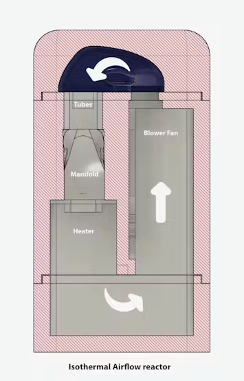
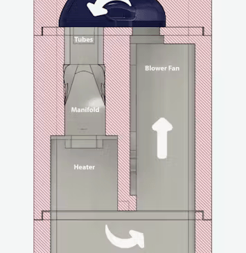
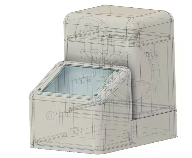
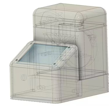
Cross-section of the vessel design showing the path of air flow
Labelled design features
Assembly of the 3D printed components for the AirFlow housing
3D components printed with Extrudr GreenTEC Pro filament


Heater and fan
The two major active components in the device are (i) ARX CeraDyna FW1275-A1041C 12V centrifugal Fan 75 x 75 x 15mm, rated at 16.58m³/h, and (ii) a 50W, 12V PTC heater element that is generally used as a component for heating car windscreens. This simple device consists of a heat resistant plastic housing and PTC heating elements attached to metal radiator fins. The heaters and fans cost around £5-£10 each retail in the UK, and about half that delivered from suppliers in China.
The fan is positioned on the side of an internal wall of the vessel to extract air from that side and to push this into the top chamber. A vent is moulded into the top surface of the vessel section, and the exit port of the fan slots into this. Note: many modern fans are manufactured with overheat sensors that cause the fan to slow at elevated temperatures - generally >70ºC. The most expensive fans are not always the best. Check what maximum temperature the fan is rated for: different fan bearings can also affect this. Running the fan over temperature may shorten its lifespan.


In addition, a custom inset has been programmed into the 3D print - positioned as a retainer for for the fan so that it can be clipped into place, along with the slot for the exit port. The fan can be permanently fixed in place by application of blobs of UV cured glue (liquid plastic), which sets after a few seconds of illumination. This quick-setting fixing agent is generally useful as a way of immobilising printed parts, components and stray leads.
The PTC heater assembly is mounted from the lower side of the vessel mid-section. It slots into a complementary notch engineered into the base. The 3D printed insets for both the fan and heater are customised for the type of component, so may need to adjusted for different models. The PTC heater is fixed in the slot with two self-tapping screws. This fixes the component firmly underneath the manifold. The mounted fan and heater are fixed in the vessel, with leads ready for connection to the electronics in the base section.
Heater and fan units before installation
Fan cutout and inset for fixing inside the vessel mid-section
Internal positioning of the blower fan


Manifold and tube rack
The manifold is incorporated by printing streamlined channels that sit under the microtube rack. The channels provide a funnel for air flow from the top section of the reactor, past the reaction tubes and into the heater.
8-microtube strips fit into the manifold with space around the the sample tubes for airflow.


Lid sitting over the manifold intake and fan exhaust
8-microtube strip inserted into the sample holder


Temperature sensor
An accurate digital sensor (MCP9808) is mounted in the top surface of the vessel, under the lid and exposed to the flow of air running towards the sample tubes and manifold. The sensor is mounted on a small circuit board at the top of the reactor, and this needs to be connected to the control electronics in the base of the device. A channel is laid down in the 3D printed vessel and provides a conduit for connecting the sensor and control electronics via a ribbon cable.
(Right: Schematic showing the path of the interior channel for the ribbon cable connected to the temperature sensor.)


The sensor is an I2C device and is connected using a 4 wire cable. A double-headed connector wire can be used. On end of the cable can be connected to the control electronics. The other end with its 4-pin plug is cut off.
The cut end of the flat cable is fed into the internal channel in the 3D printed vessel part.
The cable should be pushed through until it emerges from the other end of the printed channel.
The flat cable wires should then be separated, a few millimetres of insulation stripped off, and the wires tinned with a small amount of solder.
The leads are soldered to the MCP9808, taking note of the 4 connections to the VCC (5V), GND (ground), SCL (clock) and SDA (data) terminals. After soldering, any protruding leads should be snipped off.
The top surface of the vessel is printed with an inset, so that the board can be pushed downwards to sit flush with the surface. Ensure that the solder joints are solid. It can then be permanently glued in place.
The sensor sits adjacent to the sample tubes and provides an accurate measurement of air temperature. Technical details about the MCP9808 sensor and its use with the XOD no-code programming environment can be found here.


Control electronics
The basic hardware: heater, fan and temperature sensor need to be hooked up to an electronic control system. Based on earlier experiments, I decided to use an Arduino-compatible Mega 2650 PRO mini microcontroller board with a 4D Systems Gen4 touchscreen for interactive display and controls. (Recent advances in ESP32 hardware and displays might dictate a different decision today). The hardware combination allowed the use of simple and fast no-code programming tools (XOD and 4D Workshop) to configure the control routines and display. Further the Mega 2650 PRO board is both compact and relatively powerful. Unlike Arduino UNO compatible boards (with single hardware serial port), it provides multiple hardware serial ports, which allows easy use of dual ports for programming and screen communication. Hardware serial port connection speeds are much faster than software defined serial port communication,
In addition to the microcontroller board and display, the control electronics include a step-down voltage controller to provide a regulated 5V supply from 12V, and two MOSFET (metal-oxide semiconductor field-effect transistor) solid-state relays for microcontroller regulated, independent switching of power for the fan and heater. The compact size of the components allows the electronics to fit within the tray underneath the 3D printed console at the front of the instrument. In addition, a small piece of stripboard is used to distribute signals from the MCP9808 sensor. A diagram of the full circuit layout can be downloaded (below) either as an image or Fritzing file.


Components used for assembly of the isothermal AirFlow device
First, assemble the 4D Systems Gen4 uLCD 32DT screen to the back of the 3D printed console. I have variously printed the console section with GreenTEC Pro. If you're expecting rough handling, you can use GreenTEC Pro Carbon filament for a considerably stronger print for this relatively thin-walled console section. The 3D print design includes a cutout and inset to mount the screen neatly, and well as mounting holes for stainless steel M3x10mm bolts. The ribbon cable connector and µSD card can be added for programming the screen.
Click here for an introduction to code-free programming and use of the 4D Systems screens.


8-microtube strip inserted into the sample holder
Connecting the 12V DC supply powering the circuit


Installation of the 4D Systems touchscreen
12V power socket and 2-way split
The device has 12V DC heater which is rated at 50 Watts. This is by far the major draw on the power supply, which must be rated to accommodate this. The external 12V DC supply should be rated for at least 6 Amps (72 Watts). Suitable power supplies (also used for laptops, CCTV systems, etc.) are readily available for around £10-15 retail price. These power supplies will generally have a 2.1 mm diameter coaxial plug connector, with centre positive polarity (check specifications before purchase). The external power supply will plug into the AirFlow device via a chassis-mounted 5.5 x 2.1 mm DC power socket rated for 10 Amps.
Appropriate gauge wiring should be use for the lines handling the 12V DC supply for the heater. I used 20AWG wire for the main 12V DC lines. Short leads were soldered to the chassis-mounted power supply socket. Bare joints were covered in heat-shrink tubing. Red and black wires were used for positive and negative polarities, respectively. The 12V supply is fed into two branches, one containing a MOSFET switch for the heater circuit, the other containing a MOSFET switch for the fan and a 12V-5V converter circuit board. The two branches were supplied using a T-Tap 2-way quick splice wire connector, where the appropriate 20AWG wire leads were connected by simply clamping in the connector with pliers.
The 12V power supply wires should be connected to: (i) the input screw terminals for the LR7843 MOSFET, which is used to switch power to the PTC heater, and (ii) the input screw terminals for the D4184 MOSFET which switches power to the fan. The terminals are also used as a junction to feed 12V DC to a mini DC-DC Buck stepdown converter (OE-SD28V) to provide a 5V regulated output.
The circuit board has positive polarity pads for input (IN+) and output (VO+) voltages and a common ground pad (GND). The enable (EN) pad can be used as a switch for the output. The reverse side of the circuit board contains a trace (below: circled) that can be cut to set the voltage conversion to a set value (rather than adjustable via the onboard potentiometer) and can be set to 3.3V, 5.0V, 9.0V, 12V by bridging solder pads. The circuit requires a 5V supply, so the trace should be carefully cut and the 5V setting chosen. It is a good idea to check the output voltage before wiring it into a circuit. The OE-SD28V circuit board is small component that can be wired up, then enclosed in heat-shrink wrap to make an in-line device.
Wait before wiring the leads to the screw terminals, to allow easier assembly of the rest of the circuit.


2-way split for the 12V line


OE-SD28V voltage converter
Cut the trace on the reverse side of the OE-SD28V, then make the 5.0V solder bridge
The remaining circuit can be soldered together, to link the microcontroller board, sensor, touchscreen display and MOSFET switches via a small stripboard.
(i) cut and trim a small piece of stripboard to suit (see pattern of traces above)
(ii) Solder a 4 pin plug socket that will accept the signals from the MCP9808 I2C temperature sensor.
(iii) Connect the 5V, GND, SDA and SCL terminals on the Mega 2560 PRO Mini microcontroller (MCU) to the stripboard.
(iv) Connect MCU terminals D20 and D21 to the MCP9808 SDA and SCL on the stripboard. Connect the MCP9808 5V and GND lines on the stripboard.
(v) Connect MCU terminals D10 and D11 to the two MOSFET modules. Run the GND signals to the GND rail on the stripboard.
(vi) Connect the D3, D18, D19, 5V and GND signals to the connector for the LCD touchscreen. Leads with a 5 position in-line socket can be soldered to the terminals to allow reusable connection to the 4D Systems touchscreen connector board.


Wiring the components
The boards should be laid out in the intended positions. Hookup wire can be cut to size, ends stripped and soldered in place. Solid-core wire can be used to create a more rigid framework to keep the boards connected. The final circuit should look something like the following diagram - although alternative ports and routing of power signals can be used.
After wiring the MCU board and peripheral components, the MCU can be programmed from XOD through its USB port, and the 4D Systems display programmed from 4D Systems Workshop4 via the serial pins on the connector board. (see below for details)
The fan, heater and sensor leads pass though the mid-section vessel via ports in the 3D printed casing - and are lead out to the front space under the casing. It is necessary to block any openings between the reactor vessel and the console space that houses the electronics. I have found that Blu-tack acts as an excellent putty-like stopper that is easily removed and can be reused multiple times.
(i) The power supply routing should be attached to the relevant MOSFET screw terminals.
(ii) Connect the fan and heater leads to the relevant MOSFET screw terminals.
(iii) Connect the MCP9808 sensor cable to the socket installed on the stripboard.
(iv) Connect the display to the MCU via the 4D Systems connector board.


Connecting components to the microcontroller
Wired components
User interface
The MCU control system and touchscreen user interface were laid out using two no-code graphical programming systems.
First, the user interface was composed in 4D Systems Workshop4. This software package is provided free by the manufacturers of the touchscreen. Individual screens are composed by adding widgets in a WYSIWYG editor, and adjusting their properties by setting parameters. Screen widgets can either display status, or be used to set particular values via a range of interactive controllers. Prototype code is then loaded onto the target screen, which results in a defined set of software modules that a microcontroller can communicate with, through a serial port.
Second, XOD is a free, graphical programming environment for Arduino-compatible microcontrollers based on a dataflow model. It has good support for 4D Systems screens, and allows the rapid prototyping of control systems.
The objective was to produce a simple-to-use graphical interface for setting isothermal incubations. The prototype interface consisted of four screens with (i) a top-level status screen that included calls to three subsidiary screens that allowed (ii) setting of the target temperature, (iii) time of incubation, and (iv) screen plot of the vessel temperature over time - displaying +/- 10ºC around the set point.


Top screen
The top screen has widgets to display: current vessel temperature (ºC), current run time (min), temperature set point (ºC), set time (min), fan activity (on/off), heater activity (on/off), and buttons to start/stop the run, and to navigate to the three other control screens.


4D Systems Workshop4 widgets for Top screen
Photo of Top screen in action
Set runtime screen
The time of a run can be set from this screen (above), with a 9-position switch that is touch activated. A series of set times is provided, ranging from 5 min to unlimited. The actual times can be easily modified in software, or interactive controls added. (Most LAMP diagnostic reactions run for 60 min).


4D Systems Workshop4 widgets for Set runtime screen
Photo of Set runtime screen in action
Set target temperature screen
The set point for heating of the vessel can be set from this screen (above). A 9-position switch allows choice of commonly used incubation temperatures up to 95ºC. Additional buttons are used for fine adjustments of the target temperature.(Note: it is advisiable to use a heat-resistant thermoplastic filament such as GreenTEC Pro if temperatures above 70-100ºC are to be used).


4D Systems Workshop4 widgets for Set temperature screen
Photo of Set temperature screen in action
Temperature plot screen
Plotted display of temperatures during the run. The temperature is plotted on screen on a moving display. The current temperature is shown on the right-most side of the plot, as well as a numerical value at the top of the screen. The Y-axis shows temperatures within +/- 10ºC of the current setpoint. The X-axis represents the elapsed time, with 20 sec between divisions. The total elapsed time is shown as numerical value at the top of the screen. The yellow plot displays the activation of the heater in the control circuit, with 2-step values, high corresponding to on, low to off. In this run, the heat was continuously on, until the setpoint was approached - this was followed by a small amount of hysteresis and oscillation (<1ºC) with gradual settling. The degree of overshoot is dependent on the settings of the control software (using a XOD-encoded PID routine).
All of the subsidiary screens have a 'back' button that triggers return to the top display.


4D Systems Workshop4 widgets for Set temperature screen
Photo of Set temperature screen in action


The Workshop4 code that is required to program the 4D Systems touchscreen is described below. Individual widgets are addressable from XOD and communication between the two no-code systems is required to build an effective instrument.


Control system programmed in XOD
The second major software component of the instrument design is the control of peripheral hardware from the Arduino-compatible Mega 2560 PRO Mini board. The control software was composed in XOD, and tested with open frame hardware chassis (see descriptions here), before integration into prototype instruments.
XOD employs a visual dataflow model for composing Arduino-compatible code, with interactive debugging tools and ability to rapidly deploy control routines in simple and low-cost embedded systems...and accessible for users with no conventional programming skills.
A XOD programs are called patches, and they consist of a series of nodes that can represent physical devices or computational functions. Each node has pins that represent ports for input or output of data values or timing pulses. Input pins are located on the top of a node, and output ports are positioned at the bottom of the nodes. Programs are assembled by 'wiring' the node ports to create flows of data and timing though the program. More details of program structure and execution model are available on the xod.io website. If the reader is not familiar with the workings of XOD, I can highly recommend the Biomaker Beginner Handbook and documentation pages on the XOD website.
The XOD program that is used to control the workings of the AirFlow device is shown below.


At first glance this XOD patch looks complicated, but it can be broken down:
Touchscreen connection. First, the connection to the 4D Systems touchscreen is defined - here connected to a hardware-based fast serial port (115200 baud uart-1). A fast clock for program operations is also defined (clock with 100 msec intervals). The arrows represent values that can be shared in a bus-like way with other nodes. For example, the fast clock node shares 100 msec pulses with other nodes though the tick bus.


Master clock. A second clock node is defined, which send pulses at 1 sec intervals. A count node is used to generate a running total of the number of seconds elapsed. This value is sent to a divide node, divided by 60, and the floor node used to define the quotient (number of minutes elapsed), and the modulo node used to calculate the remainder (seconds between successive minutes elapsed). The min (minutes) and sec (seconds) values are shared with other nodes. (The watch nodes are used to show values in real-time during debugging with the hardware attached to the machine running the XOD development environment).


Set the runtime. The touchscreen contains a widget that is used to set the time of a reaction. It is configured as a 9-position rotary switch which can be controlled by touch. The setting of this on-screen device is sent from the 4D Systems touchscreen to the microcontroller via the serial port that connects them. The read-rotary-switch node reads an index value from the switch (values from 0 to 8, depending on the chosen position). The nth-input node decode this information and assigns a value corresponding to that displayed on the touchscreen controller, and shares this with other nodes as the time setting for the reaction time.


Adjust the temperature setting. The base set temperature can be modified by two on-screen buttons that can be used to jog the set temperature up or down by 1ºC. Two read-winbuttonnodes are monitor these momentary activated buttons. The boolean output of each button is fed to a pulse-on-true node which converts each button press to a pulse. Two separate count nodes are used keep a tally of the number of upward and downward button presses. These are then added to the base temperature setting, which is incremented or decremented accordingly - and the final temperature setpoint is shared as value: target.
Set the temperature. Similary, a read-rotary-switch node is used to capture the index position for the rotary switch on the touchscreen. This is used to define the base setpoint for vessel heating, and is shared this with other nodea as the value: Tbase.


Read the current temperature. The vessel temperature is read from the MCP9808 sensor. An external library (wayland/mcp9808-thermometer) provides special nodes for work with this hardware. The sensor is a sophisticated pre-calibrated device that is accurate to +/- 0.25ºC between -40 and 125 ºC. More information about the MCP9808 sensor and associated XOD nodes can be found here. The node mcp9808-device initialises the I2C device and read-temperature extracts the current temperature value, calibrated in ºC. Reads are updated at 100msec intervals through use of a wake node, which is triggered by tick pulses.


PID controller. XOD provides a node that incorporates code for a proportional–integral–derivative (PID) controller. The PID controller takes actual temperature and setpoint values, and calculates the best way to control an on-off heating circuit to rapidly reach and stabilise the temperature at the target temperature, based on three parameters, Kp, Ki and Kd. Here, a pid node is used to calculate whether to heat (+ve value) or not (-ve value). A greater node is used to check whether the output is above zero, and produce a boolean value. This is combined with the on/off switch signal through an andnode - to activate the heater only when (i) a run has been activated, and (ii) called by the pid node. The heater is activated by switching a digital-writenode (Heater I/O) connected to port (D10) that controls the MOSFET controlling power to the heater element. In this device, control of the fan is simple, it is always working when the device is powered on. If the fan was to be controlled during the run, it would be advisable to program a cooling period after the end of a run to avoid any possibility of local overheating. One could also program additional visible or audible alerts at the end of reaction times, or for errors.


Write to the screen. The device writes a number of values and parameters to different display widgets programmed into the touchscreen display. There are relatively large number of widgets on the different screens, and a corresponding large number of output nodes that send the relevant information to the appropriate screen element. A number of example are shown below, where values are sent to different, indexed digit displays via write-i-led-digits nodes. The values are updated every 100 msec due to ttriggering by tick pulses. Values are updated internal to the touchscreen controller, independent of whether they are currently displayed. A larger number of widgets and/or rate of updating can tax the rates of transmission through the serial port, so fast serial hardware communication or slower rate of updates can be helpful.


Plotting temperature changes. The "plot" screen on the touchscreen provides a historical view of vessel temperatures during a run. This is done by setting up a scope widget in Workshop4, when programming the touchscreen. The scope widget provide an oscilloscope-like display, where the size, X and Y scales and number/colour of traces can be preset in Workshop4. In XOD, instances of the write-node can be used to plot new data, and control the rate of updating. For example, in this case, the vessel temperature is plotted as a differential between the target and actual vessel temperatures. A substract node is used to calculate the temperature difference. This value needs to be converted to a pixel value that is compatible with the on-screen scope widget (multiply by 10 and clip between -100 and 100, and add to offset by 100 pixels). At the same time, a signal corresponding to the state of heating is added to the plot. An if-else node is used to convert the boolean heater signal to numerical values (30 if true, 10 if false). The numerical values can be plotted as 2-state values on the scope widget (which will take up to 4 traces). This allows the user to visualise the frequency and timing if heater activation, which can be useful for tuning the PID algorithm, and as a general indicator during normal use.

The 'code' for Workshop4 and XOD are both easy to modify and can be used to create customised interfaces.
Performance
The built microreactors have been through a number of design interations, including early prototyping experiments detailed at the bottom of this page. The devices have proved relatively easy to construct, and due to the use of precalibrated sensors, simple to implement. The vessels are generally run at around 65ºC for LAMP reactions used for diagnostics.


The reactors reach the working temperature within 2 minutes, and maintain the set temperature to within <1ºC tolerance for the duration of the run. Left: A reaction interrupted by removal of the lid after 10 minutes showing sudden drop in temperature. The elevated yellow traces on the plot shows power switching on for the heater.
The hottest external surfaces of the AirFlow reactor (adjacent to the PTC heater) reach 45ºC after prolonged running at 65ºC, otherwise simply warm to the touch.


The microreactor has been tested by running LAMP diagnostics experiments, conducted by Dr. Fernando Guzman Chavez (below). The reaction mixtures were assembled using New England BioLabs (NEB) WarmStart® Colorimetric LAMP 2X Master Mix, a kind gift from NEB.


Cost of construction
The approximate retail cost of the components was around £100 (sourced from Amazon or Aliexpress)
The major costs were due to the touchscreen and 3D print materials. (COVID supply issues elevated the cost of the TFT-LCD touchscreen). Future cost reductions might centre on choice of cheaper display, and reducing the size and mass of the 3D printed vessel.


3D printing files (STL format)
Lid
Screen and electronics console
Middle section
Base section
airflow_LAMP_v48_lid2.stl (1.1MB)
airflow_LAMP_v53_console.stl (254KB)
airflow_LAMP_v37_mid-vessel (1.0MB)
airflow_LAMP_v45_base.stl (55KB)
Fritzing circuit layout
Background to the development work
The AirFlow microreactor design came from a programme was initiated during the COVID19 lockdown. It was part of an attempt to explore different approaches to the design of microreactors. The common theme was that heated air flow was to be used for temperature control. This avoided the need for more expensive machined metal components.
The current design is based on a series of exploratory experiments, outlined below.
Rapid Prototyping methods
Project: Programmable test rig: part 1
Rapid prototyping of control systems, digital sensors and interfaces, using XOD (https://xod.io), a no-code graphical dataflow programming environment that allows rapid construction and reconfiguration of control routines and touchscreen display.
Vessel design
Project: AirLoop reactor: part 2
Project: Radial airflow incubator: part 3
Project: Modular microreactors: part 5
I tested several vessel designs including 3D printed chambers that used (i) a lateral loop of air flow, (ii) radial, fountain-like vertical recirculation, (iii) bilateral vertical recirculation and (iv) single vertical loop. 3D printing allows easy customisation of reactor designs. However, one major constraint is the poor heat resistance of many easy-to-print thermoplastics. A lignin-based polymer Extruder GreenTEC Pro was identified as a suitable material for heated vessels that might reach 100ºC.
Heat transfer
Project: Heatsinks for microreactor temperature control: part 4
Project: Modular microreactors: part 5
A range of PTC (positive temperature coefficient) resistive heaters were used as sources of heat. These ranged from small 12V, 5-10W PTC heaters (glued to heatsinks) to 12V 50-150W PTC heaters, with and without integrated fan, which are designed to heat car windscreens or interiors. A key potentially limiting factor is the efficiency of heat transfer to air, and a range of potential solutions were explored. (i) Small PTC heaters were attached to passive heat sinks and placed in air streams, (ii) various low-profile heatsinks with integrated fans were tested for efficiency of heating, and (iii) car heaters with integrated PTC elements and radiator fins for heat transfer. The latter proved cost-effective and powerful.
Air manifolds
Project: Thermal cycling airflow reactor prototype: part 8
Project: Airflow reactor manifolds: part 10
Previous microreactor prototypes showed the promise of using fan heater components for cycling temperature control. Higher powered PTC elements allow rapid air heating in small reactor volumes, which can be directed and switched using simple fans. I then printed a variety of manifold designs in heat resistant material, and designed to drop into reactor vessels as a modular unit, sitting over the fan heater component. These were intended to harness heated air flows and direct them at higher velocities across the sample tubes. Some designs included internal baffles to promote even mixing of the air streams. The manifolds were tested to demonstrate their important benefits in minimising temperature differences across multi-tube samples, and maximising heating/cooling rates.
Modular assembly
Project: Thermal cycling airflow reactor: part 7
Project: Refactoring the airflow reactor design: part 9
Project: High-static-pressure-fans-for-the-airflow-reactor-part 11
Project: Redesigning flow channels for the airflow reactor
The next steps in the project were to design reactor vessels that were modular and slotted together, with minimal air gaps. The reactor systems were designed with three potentially interchangeable sections (i) heater vessel, (ii) holder for the reaction tubes, and (iii) lid, as part of a combined system for air heating and recirculation. A modular design allows the mixing and matching of different subsystems. A simple tongue and groove interface worked well as a physical interface between 3D printed reactor components. This allowed independent testing and improvement of modular reactor components.
Future challenges
1. Continue refining the design of the vessel to reduce cost of materials and increase speed of printing. Investigate designs suitable for injection moulding.
2. Explore different display options to reduce cost.
3. Test different venting options to allow thermal cycling.
4. Introduce optics in the manifold to allow integration of quantitative imaging and analysis.
5. Add wireless communications and web-based data collection.


biomaker.org