
AirFlow PCR device
This page describes ongoing efforts to build a cheap and reliable PCR machine that combines the flexibility of 3D printed chassis design for air flow heating and cooling with low cost components and customisable control software. The design process is based on incremental trials developing 3D printed isothermal incubators for microtube reactions. The main new challenges are:
Construction of an instrument chassis that tolerates up to 100ºC.
Use of a fan for air circulation that isn't limited by thermal cut-out (most computer fans have a built-in working limit of 70-80ºC as a guard against motor stalling and burnout).
Find a simple way of switching between heating and cooling cycles.
Moving away from XOD as the control software to UiFlow2, which provides a graphical programming interface as well as Micropython compatibility, and integrated support for touchscreen interface.
Contents
Overall design
Practical construction
Heat resistant filament
Design and assembly of the base
The heater unit
AIr vent
sample holder
Conversion of drafts to final components
Interlocking vessel components
Order of assembly
Download 3D files
Temperature control
Electronic control
Temperature sensors
Thermocouples
Calibration of thermocouples
Alternative temperature sensors
Using the TMP119 wit UiFlow2
Power control
Servo operation
Calibrating the servo
Testing the vent assembly
High current devices
Touchscreen interface
First, I chose heat resistant filaments for printing prototype vessels. Extrudr GreenTEC Pro filaments were chosen due to their excellent performance in 3D printing, and heat deformation resistance to 115ºC (ISO 75 HDT/B), compared to regular PLA with HDT/B values around 60ºC. The Extrudr GreenTEC Pro CF filament is carbon fibre reinforced for even stronger prints and marginally higher heat resistance.
Second, I based the AirFlow PCR design around a small cross-flow fan. This type of fan is available in a size of ~100mm long, with metal (not plastic) housings. It consists of an elongated multi-vane fan that rotates to scoop and eject air at right angles to the axis of rotation. The motor is positioned outside of the fan housing, so that it can be kept outside a (hot) ventilated housing if needed. The fan has a 30 mm diameter, rotates at 3200 rpm with up to 0.6 cubic metres per minute air flow, and is rated at 0.15A, 12V.
Third, I designed an interlocking set of compartments to house the fan, heater, sample - and a servo-controlled vane that can be closed to allow recirculated air flow, or opened to allow the intake of cool air and exhaust heated air. The vane is 3D printed, mounted on metal bearings, and rotates through 90ºC between heating and cooling positions.
Fourth, a switch to the UiFlow2 development environment provides integrated support for M5Stack devices with built-in touchscreens. This should simplify some aspects of programming the user interface, and allow access to communications and other hardware features built into devices like the M5Stack Tab5.
Note: this project is still underway - essentially I am posting progress reports here. Design features will likely change with further development, and there is no guarantee that the final device will even work as expected! This will depend ultimately on the speed and accuracy of controlled temperature changes in the samples. However, some of the intermediate design elements might be useful in this and other contexts, so I'll update as I go...




Overall design
Based on my experiences with the design of isothermal microreactors, I used heat resistant filament to 3D print interlocking compartments that housed the heating and cooling components of the thermo-cycling device. I re-used elements from the earlier designs, including use of a cheap and effective 50W PTC heating element and 8-strip PCR tube format as sample holder. The two new elements were the inclusion of small metal cross-flow fan instead of a tangential blower fan, and addition of a vane-based mechanism for switching air flow between heating and cooling modes. The hardware elements were integrated into a single compact housing by using a series of interlocking 3D printed compartments. The dimensions of the current model are 10cm x 10.5 cm l2.5cm (~4" x 4" x 5").
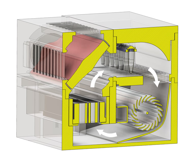
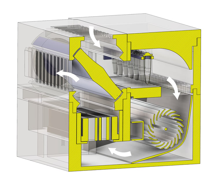
An overall schematic view of the housing is shown below, with air flow indicated by white arrows. The cross-flow fan draws air past the sample tubes and pushes it through the vanes of the PTC heater. When the vane is held by the attached servo in the 'closed' position (above left), air flow is trapped in a loop for recycling between heater and sample tubes. Powering of the heater can be adjusted to maintain a constant set temperature, similar to operation of the isothermal reactor. If the servo is used to switch the vane to the "open" position (above right) the recycling loop is open to allow the intake of outside air, and exhaust of heated air through vents suitably positioned in the housing.
The smaller-scale challenges have been to (i) adapt the individual 3D printed elements of the housing to the particular hardware components, and (ii) allow the modules to interlock for easy assembly of the entire housing, and to keep this as compact as possible. More details are shown below with the construction details.


Practical construction
The image below shows all the hardware components of the prototype vessel - (clockwise from top left) a set of 32x20x7mm steel flanged bearings, 12V 50W PTC ceramic heating element, 12V 1.8W cross-flow fan, 4titude 8x0.2mL PCR tube strip, MF90 micro servo with metal gearbox.


Below: 3D printed components of the AirFlow PCR device positioned on the printbed of a BambuLab H2S 3D printer showing the orientation and support arrangements. From top left: rear vent housing, sample housing, sample lid, base, front vent cover, vent rotor, PTC heater holder. These are prototypes, printed in white PLA for fitting. (The final versions were printed in black ExtrudrTEC Pro CF filament.) Standard settings were used for the BambuStudio slicer (0.20mm layers with a 0.4mm nozzle with checked addition of support (tree-auto, 30% threshold angle). Support material was removed with fine needle nose pliers after printing and removal of components from the printbed.
Heat resistant filaments
Applications that require higher temperature incubation demand use of heat resistant filaments to print any vessels or housings that might be exposed to elevated temperature. For example, objects printed with standard PLA filaments may start to deform under load at temperatures above 50-56ºC, and unloaded parts might start to soften at 55-65ºC. This is clearly not appropriate for PCR reactors which will be exposed to temperatures up to 100ºC.
For high temperature applications, I have mainly used filaments from Extrudr - the GreenTEC Pro series, including the CF variant, which contains around 10% carbon fibre content to provide additional strength (but require a hardened steel nozzle). The GreenTEC Pro filaments have a claimed heat stability against part deformation under load (HDT/B, ISO75) to 115ºC, and against softening (VUCAT/A, ISO306) to 160ºC. The material is easy to print with, and reasonably priced. The CF version is a useful option for parts that require extra strength due to thin dimensions or load bearing. Click here to download some more technical information from the Extrudr catalogue.
In addition a similar alternative matierla has appeared on the market: Bio HT from Filamentive. I haven't tried Bio HT, but the specifications look very similar to Extrudr GreenTEC Pro (VICAT 160ºC, HDT/B 115ºC), so may be worth a try.
Alternatively, there are high performance materials like Ultem and PEEK that offer heat resistance to over 200ºC, but these are generally expensive and require specialised printing techniques. A useful online article can be found here.


Design and assembly of the base
The base of the vessel is printed in a single piece with drop-in slots for the fan (and the PTC heater unit). The base has a 10.5mm x 12.5mm footprint. All of the 3D printed vessel components were modelled in Autodesk Fusion 360 and printed on BambuLab printers (see above). PLA filament was used in the first prototyping/fitting steps, and the final prints were made in heat resistant Extrudr GreenTEC Pro CF filament.
The base is printed to neatly fit the fan, which can be dropped in, and is held in place behind a lip at the front at the front of the vessel. The fan compartment is positioned next to a slot of the PTC heater unit (see below). The fan intake sits at the top, while the fan exhaust is directed at a slot between the compartments. When running, air is pushed laterally into the lower part of adjacent compartment, which contains the heater element.


The heater unit
Based on my experiences with testing isothermal AirFlow devices, I chose to use a 12V 50W positive temperature (PTC) coefficient heater as the heat source for the device. The component is used for automotive applications like window demisting, and is widely available from sources like Amazon and Aliexpress (usually costing in the range of £4 to £10). The device is compact (90mm x 30mm) with plenty of thermal capacity to rapidly heat air inside this type of small closed vessel to 100ºC. The PTC element is self-regulating, with a maximum surface temperature of around 200ºC. As this is above the melting temperature of the plastic housing, it still needs careful regulation, but it avoids complications with bare wire heating to higher temperatures. The element is housed in a heat resistant polymer case that provides mounting points for fixing the heater in the case, and provides a degree of insulation. The element requires a 12V, 6A supply which can be conveniently provided from a switching computer power supply, and finely regulated by microcontroller with a solid-state switch.
There is a protective upper cage that normally sits over the heating element of the heater. To keep the internal air path for the vessel as compact as possible, the cage can be snipped off neatly using cutting pliers and discarded. The PTC heater unit is then fitted into a 3D printed carrier that provides flush mounting points and a lower support that ensures that all of the air flow is directed across the vanes of the heater. The use of a separate mount simplifies the 3D printing of this section of the vessel and adds an extra degree of modularity. The connecting wires for the heater are passed through a small rectangular aperture printed in the front part of the base. When finished, this can be further plugged to block escaped air flow. Bostick Blu-Tack works well as a temporary/semi-pemanent solution, and epoxy putty can provide (very) permanent fix. The heater module is fixed to the base with two M3 self-tapping screws, ideally 16mm in the front, and 18mm in the back.


Air vent
A key feature of the AirFlow PCR device is the use of a rotating baffle to switch the flow of air from a closed circuit for heating, to a open circuit that allows intake of ambient air for cooling. This vent is controlled by a 5V electrical microservo, the baffle is 3D printed and mounted on steel bearings that are supported by a 3D printed cage that includes vents for intake/exhaust of air in the cooling mode. Schematic cross-sections of the vent module are shown below. Leftt: With the vent in the closed position, air from the heater module is directed by the baffle into the sample holder - indicated by red arrows. This forms a closed circuit with the air temperature regulated by the duty cycle of the heater. Right: Operation of the servo can rotate the baffle 90º counter clockwise into the open position. This blocks the flow of air from the heater module to the samples, diverting any heated air to an exhaust vent in the side of 3D printed module. The same movement of the baffle opens access to an intake vent above, and this feeds ambient temperature air to be drawn into the fan and cool the sample tubes. The flow of air in the closed mode is indicated by blue arrows.
The vent module is constructed as a cage, with the baffle secured inside rear and front parts, each 3D printed separately. In order to support the baffle and allow precise positioning and reliable turning, I mounted each end of the baffle in press-to-fit oversize flange bearings. These provide simple and solid mounts for the baffle. The front end of the baffle is printed to accept trimmed version of the arm supplied with the MF90 micro-servo. This provides a neat fitting socket for the geared output of the servo. (I've also experimented with standard-size servos, which have the benefit of the availability of useful 3rd party metal adapters and arms, but bulkier and overkill in terms of the torque required.) The assembly is secured with 20mm M2 self-tapping screws.


Components for the vent housing
Bearings are pressed into rear and front slots in the vent housing
32x20mm flange bearings
The flange bearings fit neatly over the spindle of the printed baffle


Printed slots in the baffle spindle
Trim and fix a plastic adapter supplied with the servo
The modified baffle attaches directly to the servo


Sample holder
The same holder has simple design - it is basically a box to connect the air flow from the vent module and pass it back to the fan unit. A support is positioned in the air flow to hold a 4titude preformed 8-tube PCR strip holder, or could be adapted with a separate wire holder for standard 0.2mL PCR tubes or strips.
The sample box has an aperture to allow directed flow of air from the baffled section over the sample tubes, and a series of vents in the 'floor' to allow flow of air into the fan intake below the sample box. In addition the lid has a curved section to help guide air flow downwards towards the cross-flow fan.


Converting draft prints to final components
In the design phase, draft parts were printed in cheap generic PLA filament (~£12/kg). As the designs were finalised, components were produced in Extrudr GreenTEC pro CF filament (~£45/kg). The GreenTEC Pro CF (carbon fibre) filament is printed under slightly higher temperatures than PLA (220ºC print head and 68ºC bed) and final prints contained additional wall loops (4 vs. 2), 25% (vs. 15%) infill density, rectilinear shell patterns and gyroid sparse infiltration patterns for additional strength. So the final prints took longer to print. (Note: I've also tried printing with Lightening infill with 5 wall loops and 5 external layers, which produces effectively hollow prints, except for some strategic internal support - with thicker walls. This produces faster, lighter prints, and with carbon fibre reinforced filaments these appear strong enough for robust use. A question remains whether the lighter prints perform better, with likely less thermal inertia.) The GreenTEC Pro CF filaments print reasonably well on Bambu Lab printers with the default settings available from Extrudr. Material profiles can be downloaded from: https://extrudr.com/en/inlt/page/material-profiles. The images below show (i) Benchy test models printed in black PLA filament (rear, left) and GreenTEC Pro CF (front, right) and (ii) an image of the print bed after printing a full set of components.


Overall, the carbon fibre filament is well-behaved and easy to print with. The Benchy prints show a little more stringing than PLA under the default settings, but this is not particularly evident on the larger microreactor components. The carbon fibre material is noticeably more rigid, and this makes removal of the support material easier, as it snaps off more cleanly than the PLA printed material. Due to the rigidity (and perhaps different shrinkage properties) of the carbon fibre enhanced material, some critical tolerances needed to be relaxed by 0.1mm-0.2mm - compared to the PLA prints.
Interlocking vessel components
After printing, the components were stripped of the support material. The components were designed in a modular fashion, to snap together where possible, and to minimise the need for fixing glue of screws to hold the vessel together. This is useful for initial testing, where the vessels can be disassembled easily, and where the modular parts can be mechanically checked, and simply replaced by any revisions without requiring major adjustments. This is a major benefit offered by the use of computer design and 3D printing. Some examples of the 3D interlocking of parts are shown in close-up below.


Order of Assembly
The interlocking nature of the 3D parts and the need to add some fixed electrical elements means that the microreactor is assembled stepwise, in a defined order. A description of the steps is shown below:


Take the 3D printed base and the 3090 cross-flow fan.


The fan should fit neatly into its half of the base, secured behind a lip printed into the front of the base.
Take the 12V 50W PTC heater and the custom holder.
Insert the holder into the base to sit over the exhaust channel for the fan. It should fit tightly.
Take the heater.
Snip off the plastic cage supplied with the heater with a side-cutter.


Place the modified heater over the custom holder, feeding the electrical leads though the conduit printed in the front of the base.
The heater should fit neat and flush onto the holder. Two M3 16mm self-tapping screws are used to secure the heater and holder to the base.
Assembly of the servo-controlled vent


Plastic adapters are supplied with 5V micro-servos like the MF90.
Trim the longer arms of a cross-shaped adapter so that it fits in the notch of the baffle.
Apply a small amount of cyanoacrylate glue to the axle of the baffle, and fix the servo adapter in place with the four 6mm M2 screws. Use gloves while working with glue!


Locate two 32mm OD, 20mm ID flange bearings with the modified baffle part.
The 32mm outer diameter of the bearing (inside the 35mm flange) should slot neatly into the front and rear parts of the vent housing.
The 20mm internal diameter of bearings should match neatly with the axle of the baffle.


Slot the baffle and a bearing into the rear vent housing. The baffle should rotate freely between the two stop points.
Place a bearing and the front vent cover over the lower vent assembly containing the baffle.
The front vent cover is secured with 4x M2 20mm self-tapping screws.


The micro-servo is placed in the custom slot in the front of the vent assembly. The metal gear of the servo should engage with the adapter on the baffle. The servo is secured with 2x M2 6mm self-tapping screws.
The completed vent assembly is a self-contained module and can be tested in isolation. The physical assembly slots tightly onto the base.
Locate the 3D printed sample container and lid.


The sample container slots neatly over the fan compartment.
The sample compartment - showing positioning of the default sample, an 8-PCR tube strip.
The completed vessel, with lid in place - awaiting installation of control electronics
Collect the trimmed servo adapter and 4x 6mm M2 self-tapping screws.
Locate the 3D printed baffle and the end of the axle that has custom printed fittings for the servo adapter.
Appearance of the modified baffle with adapter for direct connection to the servo.


Notes:
It is best to print the upper and lower vent housing pieces so that the circular cutouts for the bearings are flat against the print bed. This avoids minor distortions or remnant pieces of support that would interfere with the fitting of the flanged bearings - where a neat fit is important for alignment and spacing within the vent housing.
Different printers and filament materials may affect the size of finished parts - and fitting of drop-in or interlocking components. Of course use of digital calipers and a 'trial and error' approach can correct unexpected difference. Also. if tolerances can be improved by filing to create additional working space, and heat-resistant silicone sealants can be used to fill and glue parts together - the latter is widely available for work in engine compartments, ovens, etc. The files below have been tested successfully with Extrudr GreenTEX Pro carbon fibre filament with a 0.4mm hardened steel nozzle on a BambuLabs printer with 0.2mm layer thickness extended (5 layer) surfaces and various infills, including the minimal Lightening infill.
The attachment of the upper and lower vent pieces (to fix the rotating baffle and upper and lower bearing in place) is through 4 long (20mm) and narrow M2 self-tapping screws. Aligned holes were positioned in the 3D printed pieces to allow alignment and passage of the screws. These holes were printed with a nominal 2.0mm diameter. This allowed reliable passage of the screws through the material without overdue resistance, possibly leading to snapping the screws (seen with 1.8mm diameter settings). Different printing conditions might lead to overfilling of the narrow screw holes, so check for this.
Importantly, all self-tapping screws should not be over-tightened - to avoid stripping threads in the plastic parts.
Download 3D files
Click on the appropriate file name to download 3D design files in STL or STEP format, depending on preference.


Electronic control
I have chosen M5Stack devices as the base hardware for prototyping control software and display for the AirFlow PCR device. There are. a range of devices that offer cost-effective, state-of-the-art hardware with an excellent matching set of software development tools - including UiFlow2 which provides a dual no-code Blockly and Micropython interfaces with comprehensive built-in support for M5Stack hardware. Software tools for layout and integration of touchscreen user interfaces are fully integrated. The support for programming is especially useful for rapid prototyping by biologists (like me) whose primary expertise lies more with DNA coding, rather than software development.
M5Stack CoreS3 and CoreS3 SE.
For example, the CoreS3 family of devices (above) are based on the ESP32-S3 microcontroller featuring a dual-core Xtensa LX7 processor running at 240 MHz with built-in Wi-Fi and 16MB Flash and 8MB PSRAM. Programs can be downloaded and firmware flashed through the USB Type-C port. The front of the devices house a 2.0-inch capacitive-touch IPS panel protected by high-strength glass. Power is managed by an AXP2101 PMU and four power-path control circuits, for low-power operation. Additional peripherals comprise a microSD slot and a BM8563 RTC, enabling precise time-keeping plus sleep/timed-wake-up functions. For audio, a 16-bit I2S amplifier AW88298 drives the built-in 1W speaker, while an ES7210 audio codec provides dual-microphone input. Independent POWER and RESET buttons are located on the side; long-pressing the RESET button enters download mode via a self-built delay circuit. The Core3 device provides some additional hardware over the Core3 SE model. Below its screen is a 0.3MP GC0308 camera paired with an LTR-553ALS-WA proximity sensor. Extra onboard sensors include a six-axis IMU BMI270 and a magnetometer BMM150. The kit ships with a DinBase for DIN-rail, wall-mount or screw mounting. It can be powered by an external DC 12V (9 ~ 24V) supply or an internal 500mAh Li-ion battery. There are multiple protoboard areas on the DinBase for DIY expansion.
M5Stack supply a wide range of accessory devices that are plug-compatible via standard ports or the proprietary M5-bus. UiFlow provides built-in software support across a wide range of microcontroller, sensor and actuator devices. For example, M5Stack can supply the Dual K-meter module (~£23), which can plug into the Core3 and provide dual channel temperature monitoring with code-free access through Blockly - but also accessible through Micropython or the Arduino IDE, if required. This module is especially useful for characterising the performance and establishing control systems for the AirFlowPCR reactor. The use of a touchscreen device with comprehensive, easy-to-use software development tools is very useful during the design and testing phase of instrument design.


Temperature control
The AirFlow microreactor has several main features that must be taken into account when designing an electronic control system.
Operation of the cross-flow fan is necessary for air flow through the device. The fan needs to be powered from 12V supply and draws 150mA. A solid-state switch is used for on-off control of the fan, controlled by digital GPIO from the microcontroller.
The 50W PTC heater is capable of overheating the vessel - to the point where the heat resistant plastic can soften and even melt, so proper control of the heat cycling is essential. The heater is a relatively high current device (up to 6A, 12V) and a suitable solid-state switch is used to regulate the on-off states.
Cooling of the vessel can be regulated by servo-regulated opening of the rotating vent to allow inflow of ambient temperature air and exhaust of heated air from the vessel - as well as simply turning off the heater for fine control. It is crucial to have accurate and timely measurements of the temperatures corresponding to the samples in the vessels. The vent rotor is balanced on steel bearings, so there is relatively little resistance to turning, and a 180º 5V micro-servo is used to control positioning of the vent. The servo can draw from 10mA idling to 700mA under stall conditions and a suitable pulse driver is required to allow microcontroller regulated positioning of the servo.
In the isothermal AirFlow microreactor, I used an accurate digital sensor (MCP9808) that was mounted on a circuit board, and embedded in the inside surface of the vessel, where heated air flowed over it's surface. This worked well for isothermal temperature control, where incubation times were measured in fractions of an hour or more. However, trials for temperature cycling showed that for shorter heating and cooling times (on the scale of minutes), the temperature sensor should have a low thermal inertia, and not be embedded on the vessel wall, which contributed to thermal inertia and gave artificially slow response times compared to the actual air temperatures. Suitable candidates for fast air temperature sensors are thermocouples, thermistors and non-contact IR sensors. Thermocouples are a good starting point, but require cold junction compensation and low-noise electronics due to the small voltages involved.
Efficient control of the heating to reach a precise set temperatures requires use of a PID (Proportional, Integral, Derivative) controller. This is set up in software, and requires input from temperature sensors and control of the heater and vent.
A touch screen user interface needs to be implemented to allow interactive setting of temperature set points, timing of the cycling process, and real-time display of the reaction conditions once underway.
Further anticipated developments and tweaks are around levels of condensation seen (or not) in long thermal cycling runs, which should be minimised by the even heat transfer associated with all-over airflow, compared to heating in a metal block, and future options for integrating optical sensors for monitoring real-time PCR.


Temperature sensors
The choice of a reliable temperature sensor is critical for the design of the AirFlowPCR device. A sensor would need to be able to operate over the range of 0ºC - 120ºC, readouts need to be accurate, preferably to the nearest ºC, and it is important that the sensor be responsive when positioned in an airflow. Slow response would impede operation of the control routines. A number of candidates with low mass and high responsivity suggest themselves immediately: K-type thermocouples. PT1000 resistive thermosensors and some semiconductor sensors. Semiconductor sensors are attractive, with pre-calibration and higher accuracy, but often have limited working-range at higher temperatures. However the 100TMP117/TMP119 sensors operate up to 150ºC and are available on extended circuit boards with finger-like projects, some long enough to allow only the sensor to be inserted into a controlled temperature chamber. However, I started with K-type thermocouples, which are cheap, and operate through intrinsic physical principles, through temperature dependent micro-scale voltages produced at the junction of different metals. They are available as 'naked' fused junctions a few millimetres in length (right) that can be placed in an airstream and will respond quickly to changes in temperature. These simple sensors require careful measurement and calibration for accurate readouts, but there are sophisticated ICs that simplify this process.


Thermocouples
M5Stack offer an integrated solution for reading K-type thermocouples (i) the single KMeter unit that plugs into a Grove connector, and (ii) the DualKMeter, which can accommodate two thermocouples and is a stackable module that is compatible with the M5Stack Core series (I've used it successfully with the UiFlow2 software drivers for the CoreS3, CoreS3 SE and CoreS2 devices, but not the M5Stack Tab5 - but the KMeter unit is compatible with of these). Images of the DualKMeter module ar show above. In order to install the module in a Core3 package, the 4x M3 holding bolts in the base are removed, and the upper and lower pieces are prised apart to reveal the pin-and-socket arrangement that holds the device together. This corresponds to the the 2x15 pin M-bus, which allows electrical connection between the modules which can be stacked, sandwich-like. The series of images shows the intact CoreS3 device with the DualKMeter, separation of the CoreS3 into its component halves, and reassembly after insertion of the DualKMeter plug-in module.


The DualKMeter is connected to the Core3 ESP32-S3 microcontroller via an internal I2C bus, and communicates with a specialised chip - the MAX31855 that is widely used for handling K-type thermocouple readings. UiFlow2 provides a simple software library that allows initialisation and reading of the two channels available on the DualKMeter module, using either Blockly or Micropython. Both estimated temperature at the thermocouple junction and internal temperature are accessible. The same UiFlow2 software interface allows design and implementation of the M5Stack Core touchscreen display. So gathering and displaying readings is very easy, but standard K-type thermocouples are listed with accuracies of +/- 2.2ºC or +/- 0.75%, albeit over the mid-range of a very wide range of temperatures (-200øC to 1200ºC). Simply taking readings from a range of thermocouples indicated that the measurements were reading a few degrees high, so it was necessary to better characterise the measurements to see how these could be better calibrated.
Calibration of thermocouples
The M5Stack Core3 with DualKMeter was fitted with two K-type thermocouples, loaded with software that polled the raw temperatures (ºC) reported by the UiFlow2 software. The thermocouples were fitted into the wells of a commercial PCR machine (Applied Biosystems SimpliAmp) which was set to run at a series of fixed temperatures ranging from 0ºC to 100ºC. The thermocouple readings were compared with readings from commercial devices (i) an East Tester ET3916-08 8-channel logger, and (ii) a handheld 4-channel K/J/T thermometer data logger. Both commercial devices multiple thermocouples showed readings within a 1ºC tolerance. When compared to a physical standard (stirred ice and water), the handheld appeared closer to expected temperature than the laboratory bench instrument (0.1ºC vs 0.9ºC). The graph below shows a scatterplot of readings from the commercial handheld device (HHLogger2) compared to readings from the M5Stack Core3 DualKMeter device loaded with two different thermocouples, with thermocouple 1 attached to channel1 (TCI/CH1) and thermocouple2 attached to channel 2 (TC2/CH2). All of the thermocouples were attached to the aluminium wells of the SimpliAmp PCR machine as it was programmed to equilibrate at the series of set points. Additional duplicate thermocouples and switched channels are not shown for clarity.
It is clear that all the thermocouples show a largely linear response for the temperatures used, which would include any software adjustments for calibration in the various devices. The blue coloured line on the plot represents the measurements from the commercial handheld thermometer logger. Readings from this device corresponded closely to the expected points set on the Applied Biosystems PCR machine, and most closely matched the temperature of an independent physical reference, an ice and water slurry. So this was taken as a reference plot.
The TC1/CH1 and TC2/CH2 readings were parallel, but positively offset from the reference plot. The offsets were fairly constant over the temperature range that is most relevant for PCR reactions. This suggested that it would be possible to obtain more accurate readings by simply subtracting the relevant offset in software after readings were taken.
In order to check this and get a better estimate of the offsets required, the thermocouple readings were expressed as an offsets from the intended set points - i.e. the set point values were subtracted from the reading to produce a plot of differences across the temperature range. This is shown on the second graph below. The readings from both commercial devices sit within 1ºC of each other, with the East Tester ET3916-08 readings (∆MLog1/2) showing an approximately 1ºC positive offset - but the reading for both devices (especially the hand-held logger, ∆HHLog1/2) sit close to the expected temperatures. The readings from the DualKMeter device show consistent offsets of +2.5 to +3.5 ºC over the temperature range most relevant to PCR reactions (50ºC - 95ºC) - and only vary by a fraction of a degree across the range. This suggests that a simple one-point calibration correction can be safely applied, and greatly improve the accuracy of the measurements.
I also tried swapping the thermocouples between channels to see if the (relatively small) difference seen between the measurements show a greater effect of the electronic channel, or the thermocouple and electrode. On the basis of this limited evidence, it seems that the bulk of variation (about 0.5ºC offset) was correlated with the thermocouple assembly, rather than the electronic channels. This is consistent with the design of the DualKMeter modules, as the same chip is used to measure both thermocouples - just switched between the two by software commands. These observations also suggest that an effective way of getting more accurate measurements will be to make single point calibrations for individual thermocouples, record individual offsets, and make corresponding adjustments in software.


Linear relationship between temperature and thermocouple readings. The blue-coloured plot shows the raw plot of the temperature readings of a handheld temperature logger vs. programmed set points on an Applied Biosystems PCR machine that a thermo couple is attached to. The green and grey coloured plots show raw readings from two thermocouple attached to the DualKMeter device.
Offsets in temperature measurements for the different devices. The zero value on the Y-axis corresponds to a precise match between a device reading and the expected set point at different temperatures, from 0ºC to 100ºC. The handheld logger measurements (∆HHLog1/2, orange and grey traces) appear closest and most accurate. The other commercial device (East Tester ET3916-08, ∆MLog1/2, green and blue traces)) produced readings that sat within 1ºC over the temperature range. The DualKMeter readings (∆TC1/2 and CH1/2) were consistently offset by 2.5ºC to 3.5ºC over the readings of the commercial devices. However the offsets were constant with a variation of less than about 0.5ºC over the range of 37ºC to 95ºC - suggesting that single point correction of the offset will be an effective form of calibration.
Alternative temperature sensors
There are some alternative sensors to consider - which have benefits of working over the required temperature range, small sensor size for rapid response to changes in air temperature, and can be more accurate and/or be pre-calibrated.
The PTD1000 series of sensors are available in 'bare' form to allow quick response to changes in air temperature (see right, top). In addition, chips like the MAX31865 allow simple circuitry for readout. The PT1000 sensors work by reading temperature dependent resistance across a platinum probe. The response to temperature is linear, and does not depend on cold-junction temperature (like thermocouples). They have been long used for reliable temperature measurements,
The TMP117 and TMP119 series of semiconductor sensors can be used to measure temperatures from -55ºC to 150ºC . In particular the TMP119 is a high accuracy sensor and available in small form factor. The accompanying image (right, lower) shows a TMP119 chip mounted at the end of a finger-like PCB extension - away from the I2C circuitry. The device is pre-calibrated and accurate to +/- 0.15ºC in a range from -55ºC to 125ºC. (Many semiconductor temperature sensors fail to work well at temperatures at or over 100ºC, so this device stands out as a potentially interesting candidate to try out his these kinds of application,
One current disadvantage for the adoption of these sensors is that custom Micropython needs to be incorporated into the UiFlow2 programming environment to allow use. Given the interesting properties of these sensors, this is a worthwhile project, and would allow assembly of improved circuits using abstracted code blocks and fast prototyping in software .


Using the TMP119 sensor with UiFlow2
The I2C library of Blockly functions in UiFlow2 provides a simple, basic way of reading the TMP119 sensor. The raw temperature provided by the integrated circuitry on the TMP119 board is accessible from a register accessible via the I2C bus. The image on the right shows a breadboard with the (very small) TMP119 chip fixed at the end of a finger-like projection of the circuit board. The circuit board is plugged in to a Seeedstudio Grove Prototyping module, and wired via jumper wires and connected to the Grove-compatible connector on an M5Stack CoreS3 controller.
A simple set of UiFlow2 programming blocks allows reading of the are temperature, and application of a correction factor to get the temperature in degrees Celsius. AN M5Stack ENVII unit is also plugged in through an extender on the same I2C bus. It has an SHT30 chip with temperature sensor, and can be used as a reference for the TMP119 device. ENVII parameters can be accessed with blocks provided within the UiFlow2 environment. Both sensors provide temperature values accurate to within fractions of a degree, cross-checked by an industrial thermometer.
The probe-like form of the TMP119 sensor allows it to be inserted directly into the path of air flow in the AirFlow PCR device, through a custom slot inserted into the vessel (below, right).


Power control


Servo operation
The AirFlow PCR device requires coordinated measurement of temperature and control of the servo-regulated vent. The servo controls whether heated air is recirculated through the vessel with the vent closed, or whether the vent is opened to cool the vessel, allowing the intake of ambient temperature air and the exhaust of waste heat.
M5Stack provide a stackable module that can be used with the Core series of controllers (and the Tab5 device) to give seamless expansion of useful ports. The GoPlus2 module provides 4x servo ports, 2x DC motor drivers, 3x GPIO Grove connectors, and a lithium battery. The module costs about £15. The module allows driving of up to 4 micro-servos (similar to the one used on the AirFlow PCR device. Note: It won't handle the larger 12V type. The module has an its own microcontroller, and the CoreS3 communicates with is via an I2C bus. So there is less of an issue with potentially conflicting use of I/O ports, as they are segregated.
An expanded set of GPIO ports is required to allow control of high current devices like the AirFlow PCR heater and fan via a MOSFET solid-state switch. The use of the GoPlus2 module has another advantage. It allows the use of the cheaper CoreS3 SE device (£38) as a substitute for the more fully featured CoreS3 device (£58). Some of the camera and sensor capabilities of the CoreS3 aren't necessary in this application, and the addition of the GoPlus2 module to the Core3 SE model more than compensates.
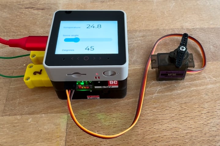
Installation of the GoPlus2 module allows access to a range of software functions in UiFlow2 that make prototyping of servo and general I/O control very easy. There are cheaper ways of doing this, but the M5Stack modules are certainly convenient and quick enough - e.g. to put together a Blockly scheme to test control systems and and cycle through different servo angle settings - as per video below.




Calibrating the servo
While the UiFlow2 software allows straightforward control of the servo and rotation up to 180º - the baffle in the AirFlow device rotates 90º, and has precise stops to allow sealing of the open and closed pathways for airflow. So calibration of the servo requires two steps. (i) registration of the axes and midpoints of the servo and AirFlow baffle, and (ii) setting the limits for rotation of the servo/baffle unit.
Servo motors work using a closed-loop feedback system consisting of a small DC motor, a gear assembly, a potentiometer (position sensor), and a control circuit board. The DC motor provides a fast, low torque turning force. A gear train is used to reduce the speed of the motor and increase torque. The potentiometer acts as a sensor attached to the final output gear to track the exact angle of the servo shaft, and the control board processes incoming commands and uses feedback to controls the motor's direction and stopping point. The servo is externally controlled by pulse-width modulation (PWM) signals. Varying the signal pulse width causes the servo to rotate to particular fixed positions. We are using a servo with a rotation range of 180º (vs. 270º or 360º). We need to set precise stopping points, as the servo controls the sealing of the baffle at the set points for the open and closed positions.
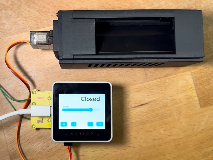
To do this, a simple piece of software was setup for the M5Stack CoreS3 SE and GoPLus2 - to allow interactive adjustment of servo rotation. The UiFlow2 Blockly and LVGL screen layouts are show below (click the images to see a larger size view). In the first step, the servo is unscrewed from the modular vent unit - to unhook the servo and baffle. The servo is plugged into a port on the GoPlus2 module, and the servo rotation is set to 90º and unplugged. This sets the servo at its midpoint. The position of the baffle in the AirFlow vent unit is also set at its estimated midpoint (see image right), which will be approximately vertical. The servo and baffle/vent unit are then reassembled and secured. Now, we just need to determine the best settings for opening and closing the vent. These will be settings that turn the servo and baffle approximately +/- 45º, but the actual optimal values will depend on the initial alignment of the servo and baffle and mechanical tolerances resulting from the printing and assembly process.
The servo and vent assembly is plugged back into the GoPlus2 module and the software allows adjustment of the angle of the servo in steps - to identify the best angles for closure of the baffle. One should look for proper seating of the baffle and sealing of the alternative paths for predicted air flow through, and avoid excessive chattering or buzzing noises coming from the servo, which might indicate stalling and pushing against the fixed seating. The optimal degrees of rotation should be noted.




Testing the vent assembly
The modular nature of the AirFlow PCR design means that the vent assembly can be easily dismantled from the instrument, and calibrated and tested in isolation. For the example shown here, the particular servo settings for opening and closing the vent were 40º open and 137º closed. Again, this can be tested by putting together a small routine that uses the M5Stack CoreS3 SE and GoPlus2 module to use these settings to flip the vent open and closed (in a loop repeated 10x in this example) - as shown in the video clip below. The UiFlow2 Blockly layout is shown right (click to enlarge).
Note: when issuing software commands to the servo, a delay of a few seconds should be included, as the servo is not able to respond to new commands while it is operating, and errors will ensue! Similarly, when using a graphical interface for interactive adjustment, wait between issuing sequential commands to the servo.
After testing, the vent assembly can be reassembled with the remaining components of the instrument. It now remains to coordinate control of the airflow with fan and heater operation.
High current devices
As well as a number of standard interface connectors, the M5Stack devices have an exposed 30-pin M5-bus connector, which provides access to number of useful output and input lines. The list of accessible signals for the CoreS3 is shown (right). For this and other useful technical information, head to: https://docs.m5stack.com/en/core/CoreS3.
Both the CoreS3 and the external devices (heater, fan and servo) need to be powered. Although the CoreS3 can be powered by a Li battery, there is not much benefit for this application, given the power requirements of the heater, which would rapidly drain anything short of a car battery. The CoreS3 can be fed from either an external regulated 5V supply or it has an internal regulator with the capacity for taking an external 9-24V DC source and dropping this to the 5V bus required internal to the device.
The heater runs at 12V and is rated at 50W, so an allowance of 5A can be made for provision of a suitable power supply. Similarly, the fan runs at 12V and ~150mA, so a minimum power supply rating of 12V, 6A would be reasonable. In addition, the servo requires a maximum allowance of 1A, but at 5V. . So a possible solution is to power the system with a heavy duty (12V, 10A) mains-powered switching power supply, and to use a step-down voltage regulator to produce the secondary 5V supply. The voltage step-down modules with the MP2482 are cheap (£2) and capable of converting 7-30V to 5V output, up to a maximum output of 5A.
Using the microcontroller to switching external power on and off to the heater, fan and servo also requires peripheral circuitry. I have used circuit boards with optically isolated LR7843 MOSFET switches, or dual D4184 MOSFETs. These are available for about £1 each.


12V to 5V down regulator
MOSFET electronic switch
assembling power routing and switches
More to come here...
Touchscreen interface
The prototype Airflow PCR device is relatively compact, and I wanted a controller that was easy to develop and customise, relatively low-cost, and that could be used to create a self-contained instrument. One option was to use an M5 Stack CoreS3 SE device as the brain of the instrument, as well as user interface. As shown above, the M5Stack M-bus interface allows rapid prototyping of extended hardware using off-the-shelf plugin modules and integrated software support in the M5Stack development environment, UiFlow2.
UiFlow2 similarly provides a no-code graphical programming environment for the touchscreen interfaces used in their hardware. In the earlier iterations of Biomaker, we used two separate software packages for rapid prototyping of combined Arduino hardware and 4D System touchscreen interfaces. However, the combining of these functions in M5Stack hardware and UiFlow2 makes the development and customisation process even faster and seamless. UiFlow2 allows graphical layout of screens, and interactive tweaking of the designs.





This is an important advantage when trying to simplify user interfaces to fit on mini-screens - to take advantage of lower costs and shrink the size of bench top devices. The M5Stack CoreS3 devices have a 2.0" (320x 240 pixel) capacitive touchscreen with seamless support built in to UiFlow2. This allows development using tailored Blockly components, and/or Micropython. Finding optimal layouts for display and user interaction can be fiddly - to allow clean fingertip control, etc. - and the ability to change parameters, reload and test in the same workflow gives the process immediacy and speed.
Even a simple control panel for a PCR device requires a multipage interface, allowing particular screen functions to be split between a number of screens, each with limited dimensions and screen space. An example is shown above, where a main display acts to summarise the parameters for the process, and is linked to sub-screens which provide space for setting parameters and display of time-dependent run data. The various points for data entry or display are simply integrated in UiFlow2.


The programmed M5Stack controllers can be placed in custom 3D printed mounts and integrated into chassis that include the target hardware. Shown above for the prototype AirFlow PCR device (the black 3D printed unit). The white PLA material was used for testing, the final version will also be printed in black Extrudr GreenTEC Pro carbon fibre filament.

More content on the way...
This is a work in progress, and more testing - with possible design revisions, is underway.
Jim Haseloff, August 2026
Parts
Uxcell F6804ZZ Flanged Ball Bearing 20x32x7mm Double Shielded Chrome Steel Flange Bearings
Thermostat PTC Insulated Conductive Type Ceramic Air Heater 50W 12V Conductive Type PTC Heating Element Up Quickly Safety
Sourcing Map Universal DC 12V 1.8W Ball Bearing Cross Flow Cooling Fan 138mm x 51mm x 49mm
Miuzei Servo Metal Gearbox 90 Servo Motor for Arduino, Micro Servo Motor Mini Servos Model Making for RC Models, Rigid Wings, Car 1/10 1/8 1/12, Robot and Smart DIY (6 Pieces)


biomaker.org